


Article
How Master Modeling Can Speed Up Product Development
Looking to increase efficiency and control in your next CAD project? Use this guide to streamline your design process through master modeling.

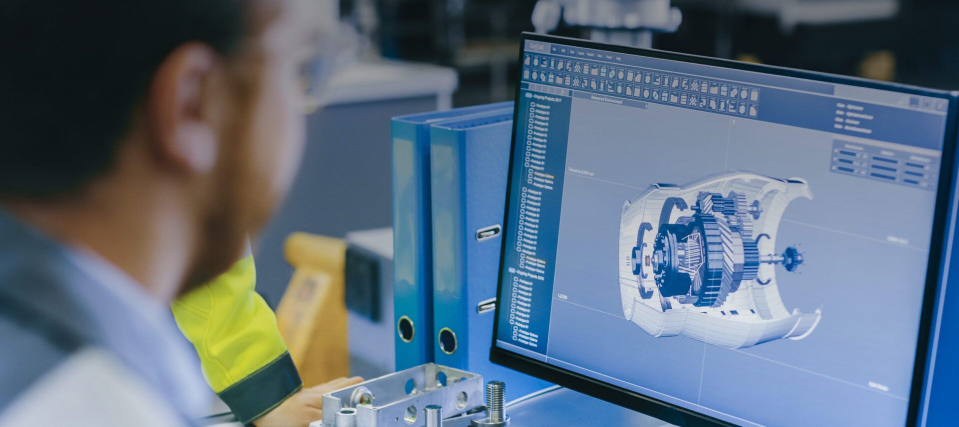
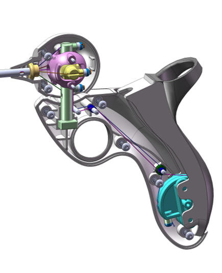
Picture this: you are designing a complex new medical product with around 100 custom parts including gears, cams, ratcheting mechanisms, and single-direction clutches, as well as user touchpoints and automatic safety lockouts. You’ve been working on this version for months. As you’re wrapping up a few finishing touches before releasing the next prototype, your boss swoops in making seagull noises and demands that the rotation direction of the primary motor be flipped.
You stare at your design on the screen and realize with growing horror that this will have a snowball effect, requiring around half of your parts to change. HALF! This would normally take around 2 weeks of effort using traditional CAD modeling, but you were smart and built the assembly using top-down design. This technique had already paid off during countless smaller design changes and will really be put to the test now. Utilizing the inherent power of your top-down model, you are able to make the requested update in four hours. When you tell him you’re done, the look of disbelief on your boss’s face is pure gold.
This is a true story, except in my case it was a client instead of my boss. Granted, they had a good reason for wanting the motor direction changed, but it was still a huge ask. What started out as a serious danger to the project schedule and budget ended up being an important win for the company. The speed at which we were able to implement the change elevated the client’s perception of M3 and played a role in selecting us as their go-to design firm for future projects. They even asked us to instruct their internal team on the use of top-down design.
When utilized properly, top-down design enables a product development team to work on a large design while maintaining a single place to define and control all component interdependencies. This simple fact—the control of all parts from a single location—boosts the speed at which large design changes can be made. Additionally, it prevents many accidental design mistakes.
Let me be clear: this is an article primarily about utilizing top-down design in 3D modeling, specifically in mechanical CAD programs. It’s written by an engineer for other engineers and designers. If you don’t use CAD on a regular basis or manage people who do, this article might be really boring. No apologies! Top-down design is awesome and powerful, and I will show you how to make it work for you.
What is top-down design?
Let’s start by explaining what “top-down design” actually means. Both “top-down”—and the more traditional “bottom-up”—are simply strategies for processing information. Top-down design can take many different forms depending on the type of project. Top-down strategies have been utilized in many different fields including computer science, nanotech, neuroscience, and management. This article focuses on the particular use that M3 is an expert in: product development.
The keystone of top-down design is an overall goal or intent. For conciseness I’m going to call this overall goal the “Vision.” The Vision is essentially the conceptual blueprint for what a system should achieve. The Vision is often somewhat abstract and each unique project will have its own way to capture what the Vision is. It might be a list of product requirements, a conceptual sketch, or just an idea in one person’s mind.
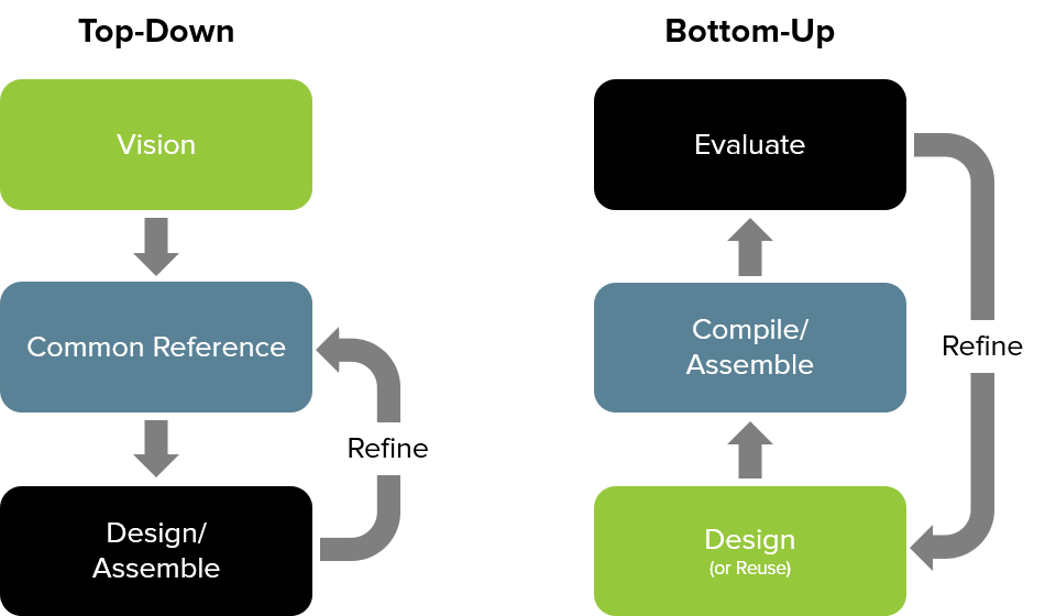
Let’s compare top-down design with the more traditional bottom-up approach.
As illustrated in the image above, a top-down process starts by defining the end goal (or Vision) and then works “downwards” to establish a common reference. While the Vision may be somewhat abstract, the common reference is more tangible. It is the physical touchpoint all components use to keep true to the Vision.
The common reference can take many forms such as a document, database, or sketch. Individual components are then built using the common reference as a…reference. Changes to the Vision are quickly disseminated to all components by simply adjusting the common reference.
Conversely, a bottom-up process begins by designing (or reusing) individual components. These components are then compiled into groups (e.g. assemblies) to create the full system. Lastly, the assemblies are evaluated for how well the individual parts fit and function together. Discrepancies and misalignments are noted and fixed in the individual parts.
Master modeling
Master modeling is simply a CAD embodiment of top-down design. There are actually several ways to employ top-down design in 3D CAD modeling including: master modeling, assembly context features, multi-body part design, and external design tables. Your options and best practices will depend on your specific CAD software and the type of project you are working on.
At M3 Design we primarily use Solidworks and Creo. Through years of trial-and-error, we have developed a master modeling approach that works best for us. You may find that a different way of incorporating a common reference into your design works better for your project or business. And that’s totally fine; you will still reap the benefits of top-down design.
The master, sometimes called a skeleton, is simply a part file created to serve as the common reference. A master model is typically comprised of non-solid geometry. Any relationship governing the interface between two (or more) components—such as a press fit or gear spacing—should be included in the master. It is also common for the master to include curves that define the outside envelope of the product.
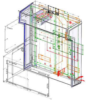
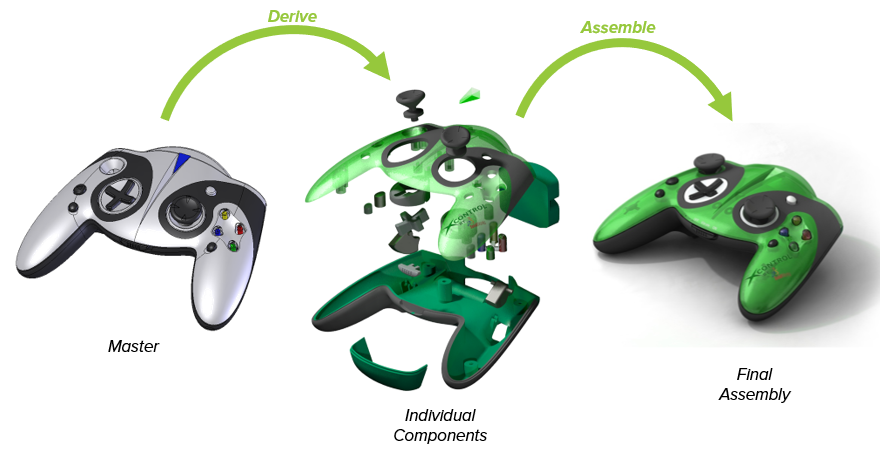
The image above is an example of what a master might look like. Although it may appear complicated, it is simply a part file (.prt or .sldprt). As previously explained, this one part will be the common reference for all components in the assembly and therefore has a lot of information built into it.
Features in a master typically include:
- Datum features (planes, axes, points, coordinate systems)
- Sketches (curves)
- Surfaces
- Solids (sometimes but not usually)
The master is merged into every component as one of the first features. It’s used to guide and inform each component’s design. Modifications to the Vision are achieved via changes to the master, which automatically “trickle down” to all related components.
The benefits of master modeling
I’ve already mentioned several of the benefits to using this master modeling technique. Let’s discuss them in slightly more detail and toss in a few additional ones.
Control design intent in one place
One of the primary uses of a master is to disseminate and control design intent across a large design with multiple designers and engineers. Examples of design intent include:
- Aesthetics
- Size/shape
- Component interfaces—such as fits, gaps, spring compression
- Complex geometric relationships—such as ranges of motion, gear ratios
- Layout information—such as bearing placement and spacing or allocated space for subsystems like a motor assembly
Rather than each engineer going off to design parts in their own little silo—and often deviating from the high-level Vision—everyone is forced to keep their parts consistent with the design intent by linking them to the master. Top-level changes can be controlled by restricting edit access to the master, if desired. Conversely, control of the master can be shared to maximize collaboration.
Huge time savings during design changes
Because the master provides consolidated parametric control over an entire assembly, it is shockingly quick and easy to implement design changes that affect every component. Simply modify the master, regenerate the assembly, and watch as EVERY part automatically updates.
Fewer alignment and fit mistakes
For good or ill, we are all human and thus occasionally make stupid mistakes. Even the most brilliant and organized designers sometimes miss a hole alignment discrepancy or broken assembly mate. A master model is not going to prevent ALL of these issues, but it will reduce the number of these “oversight” type mistakes to a fraction of what’s typical in a bottom-up design.
Control of complex surfaces across multiple components
Controlling complex surfaces that span part splits is one of the scenarios for which master modeling was originally developed. Maintaining surface continuity across parts is tedious, even for assemblies that are controlled entirely by a single designer. In a traditional bottom-up design a large block of identical surfacing features has to be maintained and kept consistent across multiple parts. A master relieves much of this tedium by placing all of the common surfaces in a single location that are then referenced by individual parts.
Master modeling doesn’t automatically solve all of your CAD problems. You still have to do the actual 3D modeling of the features…and deal with all of the typical challenges that go along with that. Zero thickness faces, strange surface kinks, demonically-possessed sketch dimensions that invert without rhyme or reason, and enigmatic “geometric condition” errors (Solidworks users will know what I’m talking about) are all still up to you to beat into submission. However, the benefits listed above are very real and should provide a strong incentive to experiment with master modeling in your own work.
Caveats
It’s not all sunshine and rainbows. As with everything in life, there are trade-offs and I would be remiss if I didn’t point out several disadvantages inherent to utilizing a master model.

With great power comes great responsibility
One of the primary benefits of a master-driven design—the ability to change multiple parts from a single location—is also one of the primary disadvantages. Because even a tiny change to the master can have a snowball effect throughout the whole assembly, making design changes require complete system-level understanding. If not careful, changing the master may “accidentally” change components without the designer realizing it.
Workflow bottleneck
Access to the master can be a workflow bottleneck for teams. Since every component interface is controlled in the master, it’s common for several people to need access to it simultaneously. There is a technique to minimize this issue that involves splitting the design into several separate sub-masters that are all linked together by a top-level master. This sounds more complicated than it really is.
Slow assembly regeneration
Updates to the master require nearly all parts to regenerate. Thus regenerating large assemblies can bring even fast computers to their knees.
Even after considering these caveats, the benefits of using a master model outweigh the disadvantages for nearly every project we work on at M3 Design. I would estimate that 90% of the CAD designs we create use a top-down approach.
When to use master modeling
It should be evident that given the caveats listed above, top-down CAD design is not well-suited for every situation. Generally speaking, master modeling is a tool best used in the following scenarios:
Early in the development process
Early in the development process the design and requirements are still fluid. Large, system-wide changes are frequent as concepts evolve. Top-down design is an efficient way to quickly cycle through multiple concepts with a minimal amount of tedious design effort.
Complex systems
Complex systems involving many parts, sub-systems, and interfaces between components are ideal candidates for master modeling. Master models help the designer plan the system at a high level and break it into smaller more manageable sub-systems before ever starting to detail individual components. It’s incredibly useful to be able to visualize and control a simplified representation of the assembly, especially for mechanisms with dependencies between various moving parts.
Examples of complex systems could be a transmission with multiple axes of rotation or a surgical device console consisting of many part interfaces.
That’s not to say that top-down design is bad for simpler systems. We often use a master even in simpler assemblies for all the benefits listed previously. But because complex systems have more parts (and potential accidental mistakes) the potential time savings of master modeling are that much greater.
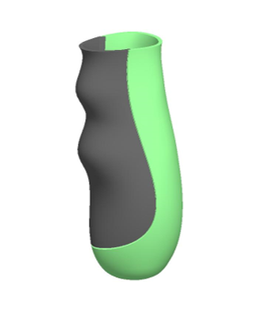
Complex surfaces in assemblies
Assemblies with complex geometries or surfaces that span part breaks are excellent candidates for master modeling. Such designs are typical for injection molded or cast components. Common examples include ergonomic tool handles and organically shaped computer mice where many parts need to match the same external surfaces.
When to use traditional bottom-up design
Although they’re less common in our portfolio of work, there are some scenarios when using a bottom-up approach makes more sense.
Iteration on existing design
It may not be worth the effort to remodel all the existing components to be driven from a master model. Even in new designs, if most parts in the design are “off-the-shelf” (purchased or reused from other projects) and can’t be modified, it doesn’t make sense to have them controlled by a master model.
Component-level revision control is required
When strict revision control of every component is required—typical with medical devices—using a top-down approach may not be the best choice. Such products cannot afford to have every single part update when making a minor change to the master.
Top-down design in practice
Hopefully, I’ve sufficiently extolled the benefits of master modeling to at least pique your interest and make you consider experimenting with this powerful tool in your own workflow.
Since we are in the consulting business, we at M3 Design are acutely aware of the hours spent on every task and are constantly optimizing for efficiency. That being said, even on the projects where we know our final CAD database will require the master and all external references removed to meet our clients’ internal Doc Control rules, we still choose to use a master model the majority of the time. The time saved in the Concept Phase with a top-down driven design more than compensates for the little bit of time required to remove the master after concept freeze.
I encourage you to experiment with this technique on your next project. While it does require a little more effort on the front end while setting up the master, the benefits far outweigh the downsides.